Very Preliminary
|
||||||
Proposed by
Jean-Marie Frère, ULB, Bruxelles,
with the technical support of
Anastase Karusho , ULB

Here we try to calibrate the solenoid used in the previous experiment.
At the difference of the main measurement mentioned above, this manipulation is slighlty more advanced (university/college rather than secondary/high school), and requires some (very usual) lab equipment.
- Using a Hall effect probe in DC currents (we have not pursued this direction for now)
- Using an
auxiliary (probe) coil, and measuring the
induced flux (and electromotive force) in AC mode (in
practice, sinus 1 - 2 MHz signal)
- Measuring
the self-inductance of the coil (this does not
measure the local flux where we place the
compass, although it is a
nice consistency check)
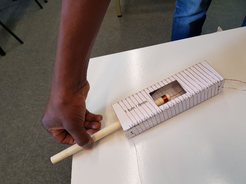
We move the probe inside the solenoid to check the variation of the induced voltage (it is very uniform!).
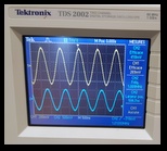
The voltage across the coil is fed to the Channel 1 of a digital oscilloscope, while the voltage across the 10 Ohm resistor is fed to Channel 2. The values are compared and provide a calibration of the solenoid.

The "probe coil" needs to be carefully wound on a non-magnetic core. The 'loose ends" of the core are tightly twisted (acting as a "twisted pari) so they don't pick up any extra induction) and connected through a coax cable to the Channel 1 of the scope .
A digital scope and a good quality frequency generator (it is useful to reach 1 MHz ) are needed.
- stray currents (induction from other sources
picked up by the coil)
- ferromagnetic materials (for instance, the
steel frame of lab tables...)
The capacitance of the scope probe causes
perturbations of some measurements (the current
can be non-negligeable at higher frequencies if the probe
X1 is used due ot its capacitance of 100pF)
Altough this can be corrected for - at the cost of
accuracy- we advise to use the
X10 probe (typically 15pF) for which these
effects could be neglected. This is particularly the
case for measuring the self-inductance of the coils.
where N/L is the number of turns per unit lenght, I the current intensity,
We now want to measure K.
For a solenoid of pitch 4mm, and a probe with n=20 turns around a circular core
of diameter 14.2 mm, we calculate (see the calculations below) the ratio of the electromotive force to the voltage across the resistor obeis:
while a pitch of 8mm for the main solenoid leads to
 For the 4mm coil, we measure for
instance this ratio to be 0.269 V / (0.418 V * 1.009
MHz) = 0.64,
 (other measurements at frequencies between 500 kHz and 2 MHz vary from 0.64 to 0.61)
while the 8mm pitch coil yields 0.361 V/ (O.583V * 2.004 MHz)= 0.31
(other measurements at frequencies between 500 kHz and 2 MHz vary from 0.32 to 0.31)

The main source of errors seems to be the fluctuations in the measurements, most likely due to stray fields in the lab environment (we did not try any shielding, but took care to place the solenoids on a big cardboard box away from metal tables)
Other errors are expected to be small: the voltage measurement is a ratio of 2 signals of comparable amplitude at the same frequency, so the linearity of the oscilloscope rather than its absolute calibration comes into play; the error on frequency is negligeable (and was checked with a separate frequency meter)
To perform this measurement, we had 2 possible choices: use the "peak-to-peak" value,
or the "rms" value. We chose the rms (the oscilloscope has a "true rms" measurement, i.e. an integration over the signal, which seems less sensitive to stray fields)
In particular for the higher frequencies, it may be necessary to take into account the actual capacitance of the oscilloscope and probes (for instance when trying the "self-inductance measurement)
The values measured are consistent (within a few %, typically 3%) with K = 1, but pending independent confirmation, we recommend, when making the Earth field measurement, to keep K explicit and to specify the geometry of the coil used.
For a probe with n turns around a core of area S, the flux is given by
and the induced
For a sinusoidal signal of frequency
and
For the stated values (main coil pitch 1/4mm or1/8mm, probe diamater 14.2 mm with 20turns) this corresponds to
We measured the self-inductance using a simple R L circuit (R =10 Ohm, generator on 60 Ohm output resistance). It is imperative to use the 10X probe, (15 pF capacitance) as the 1X probe (100pF) causes significant current in the probe at higher frequencies, which must be corrected for in calculations.
A worksheet with the explicit measurements for the 2 coils (including also the sef-inductance method) is available (follow the previous link) , with more pictures (relating successively to the self-induction and the coil methods) here.
With the data in the worksheet, we expect respectively 37 microHenry and 9.1 microHenry for the 4 mm and the 8 mm pitch solenoids. We measure values from ( 37-38) and (10-12) respectively using frequencies between 0.5 and 2 MHz.
Once again, this is just a consistency check, and not directly sensitive to the actual field at the prospective compass location.
